General Purpose ±28V Gate Drive Modules
Beginning with PD1000A Control Software release version 2022.321 (and greater), additional General Purpose gate drive modules are available. These gate drive modules provide an enhanced gate drive voltage range of -28 V to 0 V and 0 V to +28 V (VGS/VGE).
Six different sets of Standard Low-Side and High-Side Gate Drive Modules are available:
- High- and Low-Side Gate Drive with gate Drive resistors preinstalled on the module. Additionally, Gate Drive Modules with no gate drive resistors are available allowing the customer to select and install their own gate drive resistors.
- The Low-Side Gate Drive Modules have the IG and VGS/VGE Oscilloscope Probe sockets installed and the CAL SMA connector.
- The High-Side Gate Drive Modules do not have the IG, VGS/VGE Oscilloscope Probe sockets or the CAL SMW connector installed.
- Use a high resistance gate drive module (100 W or greater) for Gate Charge Measurements. Low Value Gate Resistors may cause excess ringing.
- These modules have a limited range of Gate Drive voltages: 0 to +28 Vdc and -28 Vdc to 0 V.
|
Keysight Part Number |
Description |
Output Path Mode |
|
PD1000-66848 |
Low-Side Gate Drive, No installed resistors |
Split-Path or Common-Path |
|
PD1000-66849 |
High-Side Gate Drive, No installed resistors |
Split-Path or Common-Path |
|
PD1000-66850 |
Low-Side Gate Drive, 0.0 W resistor |
Common-path mode only |
|
PD1000-66851 |
High-Side Gate Drive, 0.0 W resistor |
Common-path mode only |
|
PD1000-66852 |
Low-Side Gate Drive, 2.5 W resistor |
Common-path mode only |
|
PD1000-66853 |
High-Side Gate Drive, 2.5W resistor |
Common-path mode only |
|
PD1000-66854 |
Low-Side Gate Drive, 4.9 W resistor |
Common-path mode only |
|
PD1000-66855 |
High-Side Gate Drive, 4.9W resistor |
Common-path mode only |
|
PD1000-66856 |
Low-Side Gate Drive, 10.1W resistor |
Common-path mode only |
|
PD1000-66857 |
High-Side Gate Drive, 10.1W resistor |
Common-path mode only |
|
PD1000-66858 |
Low-Side Gate Drive, 22.0W resistor |
Common-path mode only |
|
PD1000-66859 |
High-Side Gate Drive, 22.0W resistor |
Common-path mode only |
|
PD1000-66860 |
Low-Side Gate Drive, 100.0W resistor |
Common-path mode only |
|
PD1000-66861 |
High-Side Gate Drive, 100.0W resistor |
Common-path mode only |
All of the General Purpose ±28 V Gate Drive modules provide a single-path gate resistor just as the Standard Gate Drive Modules.
Two modules, the PD1000-44848 Low-Side and PD1000-66849 High-Side modules, can be configured as either Split-Path or Common-Path. Split-Path means the module allows for different Turn-on and Turn-off Gate Resistors (RGON/RGOFF). Common-Path allows only one Gate Resistor (RG) for both Turn-On and Turn-Off. You must make the choice when you install the resistors on the module and initialize/calibrate the module.
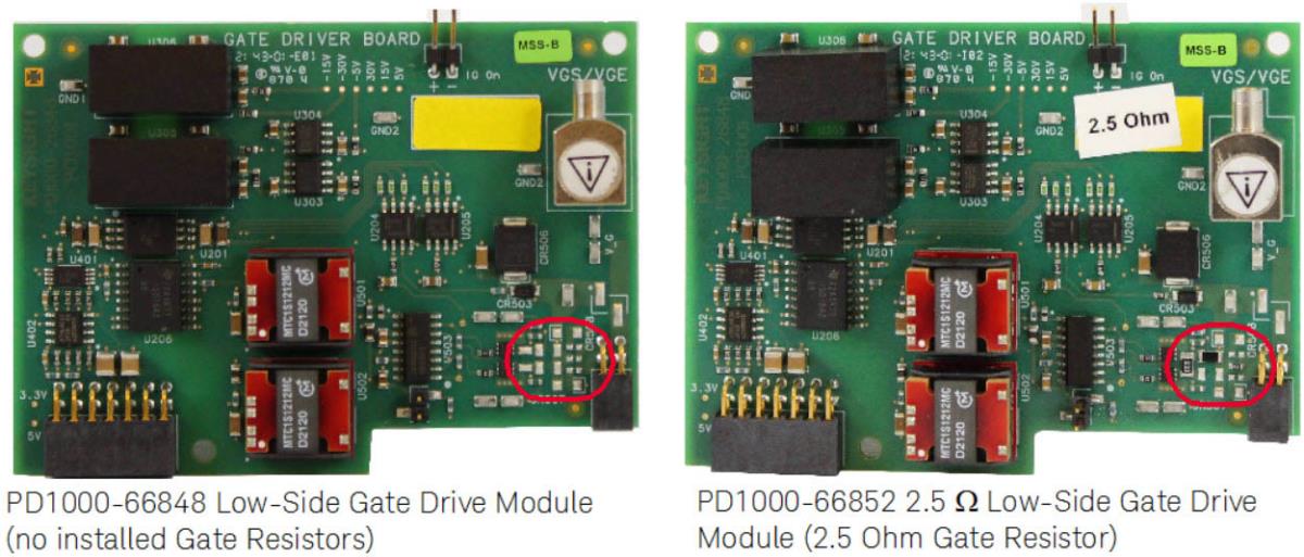
Low-Side Gate Drive Modules. Note the VGS/VGE probe sockets and IG Probe pins
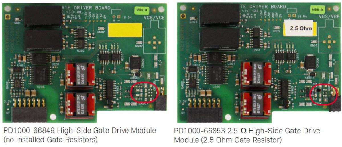
High-Side Gate Drive Modules. Note no VGS/VGE probe sockets and IG Probe pins
Split-Path vs. Common-Path Gate Drive
The original Gate Drive modules designed for the PD1500A used a single resistor to both turn-on and turn-off the FET. This is called a Common-Path Gate Resistor.
Many power electronics applications have one gate resistor for turn-on (RGON) and a separate gate resistor for turn-off (RGOFF). This is called Split-Path Gate Resistors and allows more control to turn off the device faster than turn on.
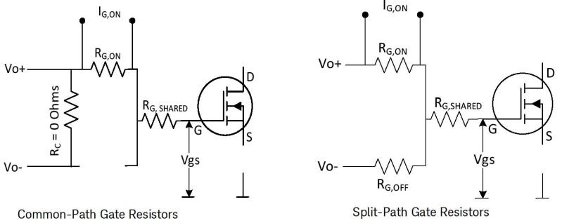
The speed of turn-on and turn-off can be controlled by having separated gate resistors. Fast switching can make the switching loss smaller though the risk of having unexpected surge or ringing becomes higher. Having control over RGON and RGOFF allows optimization of switching loss and stable operation.
By using smaller RGOFF than RGON, the charge stored in the input capacitance of the FET is quickly discharged through resistance RGOFF.
To prevent parasitic turn-on the fast drain voltage change (dV/dt) at turn-on event can cause displacement current flowing through the Miller capacitance of the FET. It generates a voltage drop across the gate resistor (RG) and lift up the gate voltage of the FET, which can lead to parasitic turn-on or false turn-on. It can be avoided by using a smaller RGOFF.
The need to measure gate current is to characterize gate charge characteristics. The gate charge characteristics are normally measured by measuring gate current over time at the turn-on event. In order to avoid error caused by ringing and surge current, a large gate resistor (100 W or larger) is used for gate charge measurement. For gate charge measurement, a large (e.g. 200 W) resistor is installed on the gate driver board and used for both turn-on and turn-off events.
In this case, only one current path is necessary to monitor gate current for both turn-on and turn-off. If separate gate resistors are needed for gate charge measurements, the PD1500A measures only the RGON gate current.